


Building the RV-4 was not difficult, as I have come to expect from Hangar 9 ARF's.
Text, photos and video by Tom Hintz
Posted – 11-7-2018
Hangar 9 is one of my trusted RC airplane manufacturers and that will continue. However, I did find a few “issues” while building the Hangar 9 RV-4 that strayed from what I have come to expect from z favored manufacturer. It is important to note that none of these issues compromise how the Hangar 9 RV-4 flies. Nor do these issues complicate the building to any great degree. They are more aggravating than anything and add just a bit of problem-solving to the process.
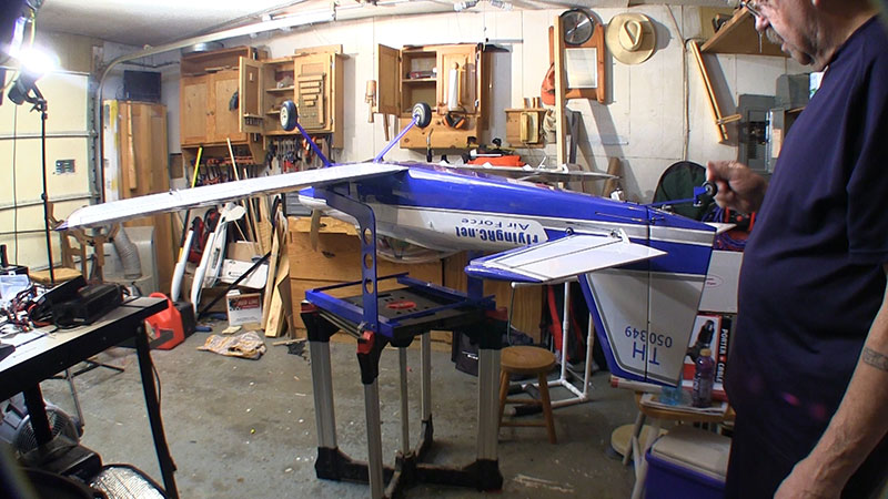
The Hangar 9 RV-4 has a wingspan of 85" (2.16m) and a wing area of 1551 sq in (100.1 sq dm) which works out to a relatively light 25.3 oz/sq ft wing loading. The fuse is 72 in (1.83m) long and the projected flying weight is 17-19 Lbs (7.7- 8.6 Kg). My Hangar 9 RV-4 weighed 18lbs even with a full 16oz gas tank.
The Hangar 9 RV-4 has been designed to use electric or, as in this Review, gas power in the 30cc range. The Horizon web site has complete lists of needed components for either power source. See Resources below.
Naturally when a 30cc engine is suggested, the RC-sector in my brain mind interprets that to be 40cc. That also provides a justifiable excuse to Review the VVRC 40cc Twin "Classic" gas engine from Valley View RC. FlyingRC.net viewers have been asking for this engine Review and that will be posted separately soon after the Hangar 9 RV-4 review is completed, and I get some flight time on the engine.
To make transport realistic in todays’ smaller vehicles the Hangar 9 RV-4 uses a two-piece wing strengthened by a 1" (25.4mm) diameter, 31”-long aluminum wing tube. The horizontal stabilizer is also removable to further reduce the overall dimensions for transport if necessary.

Access to the wing bolts cold be a bunch better but
if that is my biggest concern, I'll get over it.
A welcome discovery with the Hangar 9 RV-4 was finding all its control surfaces hinged at the factory. Hangar 9 decided to use a hinge that uses a long, wire that runs through all the hinge points on a control surface rather than individual hinge pins in each hinge. The 90-degree bent end of that wire is buried in a small slot at the end of the control surface. Very clean, very secure but can be disassembled later if need be.
All control surfaces feature contoured edges that virtually eliminate gaps that can cause flutter or otherwise impact performance. This kind of hinging is not fun to install because of the precise alignment required of the components to insure smooth, bind-free operation. I was happy to see that Hangar 9 had done that work for us.
The Hangar 9 RV-4 comes with an “interior” that is not meant to win scale contests but does look way better than an empty canopy. Included is a “dashboard”, mock roll bar and seat back. Most notable is the painted pilot in the correct scale for the plane. This is more often an extra expense with most planes.
I freely admit that I suck at installing large canopy’s and that applies to building the Hangar 9 RV-4. I could not get the canopy to sit completely flush on the fuselage so resorted to my normal screws and canopy glue. When the glue dries I will add rubber-backed washers to the screws to help prevent splitting.
A good portion of the FlyingRC.net viewers and myself like twin-cylinder engines so I decided to put the VVRC 40cc Twin "Classic" in the Hangar 9 RV-4. Watch for my stand-alone Review of the VVRC 40cc Twin "Classic" coming shortly after the Hangar 9 RV-4 Review is completed.
Mounting the VVRC 40cc Twin "Classic" is simple and using the standoffs included with the Hangar 9 RV-4 kit, achieved the 7” firewall to prop washer dimension I found on a forum. The Hangar 9 RV-4 instructions do not provide this dimension for some reason. That 7” seems to work fine as the cowl matched up to the spinner and was easy to cut.
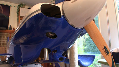
The cowl is wide enough for many two-cylinder
engines but needed cutting along the bottom to clear
mufflers.
The Hangar 9 RV-4 cowl is sleek and offers plenty of side-to-side room for my VVRC 40cc Twin "Classic" twin cylinder engine. However, things got a bunch tighter when I started cutting the cowl to fit around the can-type mufflers that came with the VVRC 40cc Twin "Classic".
The Hangar 9 RV-4 cowl fits the fuselage tightly which is a bit worrisome as a friend pointed out that cowls have been known to crack under that strain. Add the vibrations of a gas engine and the cowl mounting points demand checking frequently.
In todays’ world of ultra-precise laser-cut airframe components (and openings) it irks me to no end to have to carve reputedly standard-sized servo openings, so my standard-sized servos will fit. This carving was limited to the fuselage servos with the Hangar 9 RV-4. The servo mounts in the wings fit fine as produced at the factory.
For the Hangar 9 RV-4 build I used 8 Hitec HS-5665MH servos, all with stock rotation and direction, dual ball bearings and metal gears. These servos are 1.6" x 0.8"x 1.5" (41 x 20 x 38mm) which makes them “standard” size. They weigh 2.1oz (60g) each and have the traditional 24 tooth (C1) output spline.
As is my usual way, these are high-voltage servos that are compatible with 2-cell 7.4V LiPo battery power. Though a bit overkill for the Hangar 9 RV-4 the torque of 122oz/in. (8.8kg.cm) on 6.0V or 139oz/in. (10.0kg.cm) on my 7.4V these servos will fit the needs of more planes down the road if I take them out of the Hangar 9 RV-4.
The only programming change I made to the Hitec HS-5665MH was to turn on the OLP (overload protection) and set it to 30%. This drops the voltage in the servo if it stalls. I firmly believe many “bad” throttle servos (mine included) were actually killed by operating in some level of stall and simply burned out. I used my HiTec HFP-30 servo tester/programmer and have a full Review of this tool listed in the Resources section below.
While most of the Hangar 9 RV-4 assembly has been going well, the rudder pull-pull installation has proven to be frustrating for me and others. The photos in the instructions show the two elevator and the rudder servos mounted with their output shafts towards the front of the plane. The written instructions describe this orientation as well. The problem is that there is no way this works with the 3” double rudder control arm specified in the instructions. The photos appear to show a much shorter double rudder control arm that clears the elevator arms.
I turned the rudder servo 180-degrees and found that I still needed to grind the outside edge of the HiTec control arms used on the rudder servos a bit to insure clearance between them and the 3” rudder double arm at full throw.
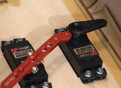
I had to mess with servo arms a little to insure
clearance.
Complicating this is that the rudder control horns have holes that are much wider than the 3” rudder servo double arm. If we use this pull-pull system as is, one cable will go slack when the other pulls the rudder. Both cables are housed in plastic tubes so they won’t snag anything when going slack but that makes the rudder “feel” odd and can give irregular rudder response. The fix is to drill new holes in the rudder control arms at the same 3” width as the holes in the rudder servo control arm.
While making this pull-pull modification I also swapped out the metal clevises supplied in the kit for DuBro 4-40 ball links. Putting a clevis in the rudder fiberglass control horn is one thing, putting another metal clevis in the aluminum servo arm just isn’t going to happen in my planes. Adding the ball links is too simple and too cheap.
After installing the VVRC 40cc Twin "Classic" I found that putting the throttle servo in from the bottom gave me a straighter shot at the throttle arm on the Walbro carb. A removable panel in the bottom of the Hangar 9 RV-4 fuse makes this easy. A metal rod and plastic tube are supplied in the kit for the throttle linkage and would work fine. However, I decided to make up a carbon fiber throttle rod with titanium ends that I get from Central Hobbies. See Resources below.
This throttle rod is super rigid and remarkably light. One note of caution: I had to bend one of the titanium ends a bit to perfect the alignment. Resist the temptation to grab a pliers and bend the end. Titanium doesn’t bend well and will likely snap off. I use a propane torch to heat it up (before final assembly of the rod) and make the bend while it is pliable. I also use DuBro 4-40 ball links on this rod.
I used the supplied tail wheel assembly because it uses a hard linkage rather than those insidious little springs that I automatically smash with a (big) hammer to spare anyone else the anguish of trying to install them. However, I discovered another “unlike Hangar 9” error in the related instructions.
They give a beginning dimension of 4-5/8” back on the rudder from the hinge line for the first mounting hole for the bracket which is wrong in a big way. I laid the parts out and found that 1-inch from the hinge line to the first screw in the rudder bracket is about right. You can see in the instruction photos that have the parts in the correct positions but also shows the erroneous 4-5/8” dimension. I wonder if this part of the instructions came from a much larger model that uses a similar tail wheel design and the dimension never got changed to the one that fits the Hangar 9 RV-4.
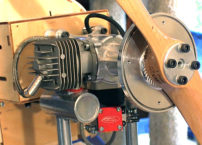
The Valley View RC twin-cylinder 40cc engine is
more than enough power for a plane this size.
The Hangar 9 RV-4 comes with a fuel tank that is probably more than sufficient. I nearly always swap out “stock” tanks for more modern designs that I consider better for tossing the plane around, often ending up in odd positions. For this build I chose the VVRC 16oz, 3-line gas tank. We have used these tanks in the past with very good results. I like the way the tanks are built, and the clear tank material makes it easier for me to see how much fuel is left so I can better judge my timer setting. They also have an aluminum down tube on the fill line that eliminates foaming when filling the tank. This way you get fuel out of the over-flow line when its full, not when the foam gets high enough.
Of course, most importantly is the consistent flow of fuel, even when the level is getting low. There is something about the felt-wrapped in-tank clunk/pickup that allows it to suck up virtually every drop of fuel. I have flown a tank like this dry and the engine runs fine until it just shuts off, like I threw the kill switch. My bad, not the tanks.
Hangar 9 decided to use interior wing bolts placed at the rear of the wing and near the bottom of the fuselage interior. Complicating this is that the elevator push rods and rudder pull-pull cables run above the wing bolt locations. The wing is supported by a good-sized aluminum wing tube, so the wing bolts are there only to keep the wing panels from sliding out.
I found that if I turned the rudder double control arm to one side I had much better access to one wing bolt. Turn the rudder double arm fully in the other direction and installing the other wing bolt is just as easy.
The Hangar 9 RV-4 comes with pre-installed wing tip lights. The manual does mention them, but the following is the total instruction provided for enabling them.
“The wing tip light is designed to operate on voltages between 6-12 volts. Use an appropriate battery and controller when connecting the wing tip lights.”
Sounds like Hangar 9 expects those who will use the lights to already know how to hook such a system up. I wanted to make the lights work but had no clue how to do that. The bare ends of the light wires provide no clues. Fortunately, a friend of FlyingRC.net suggested a simple way to accomplish this.
I used an RCEXL Opto Gas Kill Switch (link in Resources below) powered by a 7.4V, 2600mAh LiPo pack, plugged into a spare channel in the receiver. The battery is overkill, but I already had it. You can either assign a switch to this channel with which to turn the lights on and off or, as I did, use a mix suggested by the same friend. I made a simple mix between the Gear channel (where the flaps are assigned) and AUX3 where the kill system was plugged in. Flaps were assigned to the D switch on my Spektrum DX9.
With this setup the wing tip lights only come on when the flaps are deployed. I think this is more realistic and just makes more sense than having them on a dedicated switch that would allow me to keep “flashing” them incessantly.
The last step in my builds is setting the CG. Getting the CG right can mean moving the battery packs or other equipment to avoid adding unnecessary weight, so I want to get this handled now. When adding weight is necessary and I want to “build that in” to keep it hidden when that is possible.
Next up is setting all the control surface throws, finalizing any servo or radio programming and re-binding the transmitter to the plane to set the failsafe points. We will be producing a separate story on that process soon. Watch the How-To’s section for that story.
Hangar 9 RV-4 product page – Click Here
Carbon Fiber Push rods – Central Hobbies
Installing Pull-Pull Systems
RCEXL Opto Gas Kill Switch
Valley View RC 16oz, 3-line Fuel Tank
Hitec HS-5665MH Servo info
HiTec HFP-30 Servo Tester/Programmer Review