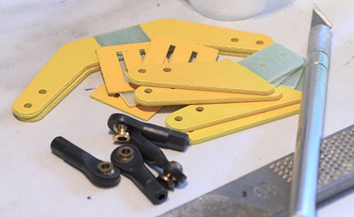
The horns and linkages included by Hangar 9 are very good and all
will be used on my Timber.
Installing control horns – permanently this time
Text, photos and video by Tom Hintz
Posted – 2-28-2020
Note: This is the first of a new style of content on FlyingRC.net. It is part Review, part How-To. In this case it shows how I install the control horns used on the Hangar 9 110” Timber ARF. Since I am a one man shop this type of content helps me cover more editorial ground without needless duplication.
One of the things I like about Hangar 9 planes is the stout control horns and linkages they typically include. The Hangar 9 110” Timber has tough, fiberglass control horns that are popular in many types of RC planes. The installation of these horns as depicted in this article is typical of many models today and the procedures will carry over too many other planes, occasionally with small differences. Always follow the instructions for that model.
My usual starting point when assembling a new plane is to glue the control horns in the control surfaces. But like too many others in the RC world, I used to blow through this task considering it too simple to screw up. Of course, that dramatically underestimates the universal human fallibility that impacts the RC community on an equal basis with the rest of humanity.
During a maiden flight of one of my 3D planes, the control horn on one of the elevator halves pulled loose, but not all the way out. The cured epoxy on that control horn had pulled free from the wood, but its rough surface acted like a barb, effectively wedging it approximately half out of the surface. That left me with one centered elevator half and the other stuck at about half its throw up when the stick was centered. I managed to get the plane down in one piece, but all the way to the ground I vowed to never be flippant (say stupid) with gluing control horns again.
Width on Width
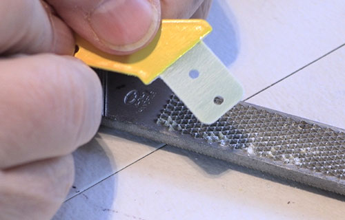
A simple woodworking rasp does a great job of roughing up the glue
surface on the horns for better bite.
Something I do prior to installing full-width rudder pull-pull horns is measure the distance between the holes to be used for the ball links. This is easy to measure now, much harder later when we remember it after the rudder is installed.
For the rudder to function predictably we need to have the cables connected to the rudder horns at the same distance apart as the ends connected to the servo control horn. If these cables are mounted wider at one end than the other, one cable will go slack when the rudder deflected to either side.
I learned this when a friend flew one of my planes and said the rudder felt odd. He looked at the plane later and found that the cables were considerably farther apart at the servo than at the rudder. After remounting the cables so the distances were very close to the same at both ends, the rudder became smoother and more predictable. This is where I realized that there was something to be gained by paying attention in geometry back in high school.
Anti-Slick
Most instructions prescribe roughing up the glue surface on control horns. I used to make several swipes with rough sandpaper making scratches in the horns surface that I convinced myself was enough. Before I could knee-jerk my way into killing control horns with cutting tools, I recognized the need for a more effective but controllable way to rough the surface.
I came across a woodworking rasp in my drawer and found that I could rub the control horn surface that needed to be roughed up on that and make decent scratch patterns evenly rather than too deep in one area. I use the rasps flat surface (most have curved faces also) as it is easier to be consistent on the area across the glue surface of the horn. On double-ended rudder pull-pull horns I use the curved side of the rasp to rough up only the center portion that will be glued within the rudder. Also, I can make the scratch pattern roughly parallel to the surface of the wood giving it a bit more” tooth” for a stronger bond.
Localized Sticky
One of the harder parts of installing control horns is coating the inside of the slots with enough glue, usually epoxy. I have sought disposable syringe-like tools but haven’t found anything that is close to cost effective on my real-world RC budget. For me, a slightly carved Popsicle stick makes the best application tool.
There is an unwritten rule in the adhesive kingdom that whatever glue you are using sticks to everything you don’t want it to and magically migrates all over the plane. Recognizing that the first tools I get out when setting control horns is my alcohol spray bottle and a bunch of paper towels. That is followed by masking tape I use to surround some of the harder to reach slots that make final clean-up easier.
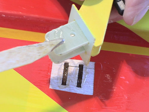
Many control horns have a flat plate that is glued to the surface surrounding the horn to increase its security. I assemble them onto the horn/s, push them into their slots then trace the outline of the plate on the covering. With a new hobby knife blade, I cut away the covering just inside of that trace. If the covering is loose, this is the time to iron it down.
I use 30 and 45-minute epoxy for installing control horns, mixing small batches to install a few horns at a time. Nothing good comes from trying to install a bunch of control horns before the epoxy begins setting up.
I use my Popsicle stick tool to work epoxy down into the slot. I also “butter” the glue surface of the control horn in the slot and working it in and out a few times also helps spread the glue more evenly.
Before the epoxy can set up, I check the horns for alignment, most should have the linkage mounting point directly over the hinge line. I also be sure the horns are square to the surrounding surface and tape them if need be to hold them square while the epoxy cures. Wipe up any epoxy that squeezed out, remove the masking tape and clean the area up. It takes longer to explain this than to do it.
Spaced and Squared
I use a carved wooden stick to apply epoxy in the slots and to the
horns and plates. It's hard to get too much glue on them but easy
to apply too little.
In most cases the factory-cut slots for the control horns are very square to the surface. I still check them and if there is a “lean” to one side or the other I use masking tape, run over the top of the control horn to the end of the structure to pull it back into square until the epoxy cure completely.
Along with adhesive security we need to pay attention of even small variances from 90-degrees to the surface in which they are installed. This is particularly true at the rudder and elevator/s where there is often little room between those linkages as they move through their arcs. If one or more control arms is installed at an angle that already minimal spacing can be compromised. A conflict between linkages could lock them up, holding their control surfaces at an uncontrollable angle when you release the sticks. The result is seldom pretty, and I think happens more often than we think. I personally have found this twice on planes that had severe control issues but were saved by talented fingers on the sticks or pure luck. Later, because they were still intact, we found the control horns running over each other, and were able to re-create the locking of the control surfaces.
It is increasing common to find dual control horns, mounted side-by-side with a ball link sandwiched between them. Here again, the factory slots are usually very close to square, but we have the additional concern of those horns remaining parallel to each other while the epoxy sets up.
When working with dual control horns I take the extra step of getting out the ball link assemblies meant for those horns. After prepping the control horns by roughing the glue area, I install the ball link and bolt to be sure they stay aligned throughout installation and curing of the epoxy. We don’t have to tighten the bolt down, just pull everything together while the epoxy cures. For me, adding the ball link and bolt makes installing dual horns easier and faster.
Many larger rudder pull-pull systems use dual control horns that pass through the rudder structure, projecting from both sides. Installing the ball link assemblies on both sides guarantees that the horns remain in the proper alignment after the glue cures. On these horns I put one ball link and bolt in one side, install the horns with the adhesive applied, then install the other ball link. Now I can check to be sure the dual arms are square to the rudder and know that they are also parallel.
Conclusions
Too many RC planes are lost to simple, preventable errors occurring during assembly. The era of ARF (almost ready to fly) kits sometimes lulls us into complacency when it comes to seemingly simple tasks, like installing control horns. Whether you are new to the hobby or have been doing it for decades, as had I before almost killing a plane with a loose control horn, paying attention to the details is a simple way to save a ton of crash repair or replacement money.
Have a comment on this Review/How-To? – Email Me. Back to the Reviews List Back to the How-To’s List
All Flyingrc.net written, photographic and drawn materials are property of and copyright by Tom Hintz and Flyingrc.net 2013-2021 Materials cannot be used in any way without the prior written permission of the owner.