|
|||||


FlyingRC.net is a
Veteran-Owned site.

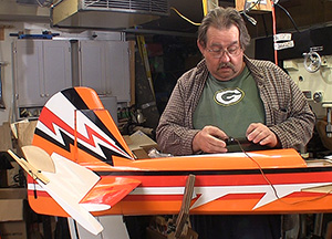 |
Installing servos is easier for me since I started using a HiTec programmer. Now I can set the servo up without any other radio equipment when it is easiest to do and do the fine tuning (if needed) later. Click image to enlarge |
RedwingRC 50cc Yak 55 Build - Segment 2
Servos, linkage, wheels and motor
Text, photos and video by Tom Hintz
Flight video by Gihad Jawhar
Posted - 3-30-2015
In this segment we install the servos, landing gear and motor in the RedwingRC 50cc Yak 55 and begin determining the best locations to get the CG right. On this RedwingRC 50cc Yak 55 with a 50cc engine the CG is supposed to be 158mm (6-7/32”) back from the leading edge of the wing. Getting the CG right is important on any plane but with those immense control surfaces and long tail moment on the RedwingRC 50cc Yak 55 CG is crucial to both the performance and the survival of the plane.
Servos
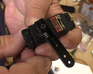
Because their locations are fixed I began installing the HiTec HS 7954SH, high voltage servos I am using on this plane. This is a digital, programmable servo that puts out 403 oz/in of torque when fed 7.4V of power. They also have tough metal gears and dual ball bearing support to withstand the resistive forces of the huge control surfaces.
I added 36” extensions to the elevator servos and 12” extensions to the aileron servos. The rudder servo should not need extensions. While many use the plastic safety clips on the servo/extension plugs I use shrink tubing as it is very secure, very light and resists catching on structure as we feed the extensions through the planes internal structure.
I use special socket head screws from Micro Fasteners for securing servos. The hex type socket makes driving these screws so easy drilling pilot holes is seldom necessary. Also, having to reach inside the horizontal stabilizer as on the RedwingRC 50cc Yak 55 to secure the elevator servos is far easier with these screws on the end of a hex driver.
 |
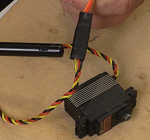 |
The RedwingRC 50cc Yak 55 has huge control surfaces so I used HiTec HS7954SH high voltage servos (left) with just over 400 oz/in of torque! I use shrink tubing to secure servo extension plugs (right) and in addition to the security it makes getting the wires through the structure easier. Click images to enlarge |
|
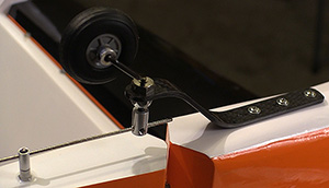
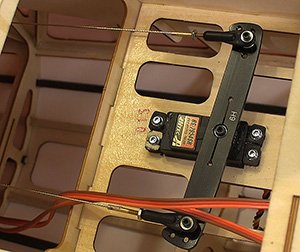
The aileron servos have two options for mounting, one internally and a second in a normal upright bay. I opted for the upright mount and used my fancy socket head screws to mount them. RedwingRC supplies nice turnbuckle linkages that make dialing the control surfaces easy with absolute precision.
Though the RedwingRC 50cc Yak 55 comes with very stout carbon fiber control arms I opted for the Hangar-9 aluminum arms that have been giving me the warm fuzzy feeling since I returned to flying bigger planes. These arms are very tough plus feature pinch bolts that make falling off of the servo spline all but impossible.
Running the aileron servo cables down through the wing is simple thanks to wide open bays all of the way. Not having a pull string installed at the factory is not an issue at all. I did add a small plastic tie just inside of the root to secure the aileron cord to the structure so it can’t slip back up into the wing during transport.
Pull-Pull
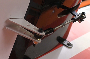
On the rudder servo I had to use an inner mounting position on the large 4” Hangar-9 aluminum pull-pull arm to match the 3-3/8” spread of the rudder control arms. If we do not have the same width at the servo and rudder one cable will go slack each time the rudder deflects. The included carbon fiber pull-pull servo arm has this spread built in as well.
Also, I am partial to the Sullivan pull-pull system that uses solder style ends on the cables. The pull-pull system that comes with the RedwingRC 50cc Yak 55 is absolutely capable and well designed for this use. I am just set in my ways and like the clean look of the Sullivan pull-pull installation even though it is a bit harder to assemble and setup initially.
There are two theories on pull-pull systems. One says the cables should cross on the way from the servo to the rudder. The other theory and the one I accept is that the cables remain separate all the way back. There are good arguments for both installations; I choose to go with the one that eliminates the cables rubbing on each other where they cross.
Landing Gear
 |
 |
The tail wheel (left) works very well and is easy to install. t pull-pull system that comes with the RedwingRC 50cc Yak 55 is more than capable. I am just used to using the Hangar-9 arms and Sullivan cable system. Click images to enlarge |
|
The tail wheel installed as per the instructions with one exception. The photos in the instructions show a cavity near the tail for installing blind nuts. This must be for a different plane (or version) as the RedwingRC 50cc Yak 55 comes with wood screws that go into a block built into the bottom surface of the tail. I cheated the carbon fiber tail gear strut as far forward on the plane as I could and still get all of the screws into the wooden block. I’d like to get the pivot point for the wheel directly over the hinge line but it is close enough as it is and I would find out that it works well this way.
The main gear came with four Phillips type screws with lock nuts that I believe were meant for the landing gear. I changed them out for 1”-long 6/32 hex head bolts with lock nuts so I could get them tighter. I am not a Phillips-friendly kind of guy, sorry.
The spatz (wheel pants) needed a bit of trimming to get rid of a bind at the center of the tire tread. A couple minutes with a rotary tool cleared that up and the 3.5” wheels run nicely with a bit of grease on the axles. I like touch and go’s and have learned to grease wheels during assembly before the squealing starts. I think the spatz are part of the YAK look and I like that RedwingRC resisted the cheaper simple full wheel pants.
I purposely have been focusing on fixed-position equipment in this segment so I can play with location of the batteries and such to try and hit the CG without adding weight if I can. The Yak design includes a long tail moment that can make hitting the correct CG difficult if you are not thinking about it while installing the components.
The last thing I did for this segment was to install the wings, the cowl (muffler taped to the outside for now), prop and spinner and checked the CG for the first time. Not surprisingly it came out roughly 1” back from the desired spot. I had the batteries forward in the fuse but have room to get everything a bit more forward.
In the next segment I will mount the electronics, motor, ignition, muffler, fuel tank and do all of that while frequently checking the CG. The RedwingRC 50cc Yak 55 is beginning to look like an airplane and the weekend is coming…..
 |
|
RedwingRC supplies high end hardware including true turnbuckle control rods (left) that are easy to dial in perfectly. Click image to enlarge |
|
RedwingRC 50cc Yak 55 Segment 1 - Click Here
RedwingRC 50cc Yak 55 Segment 3 - Click Here
RedwingRC 50cc Yak 55 Maiden 1 - Click Here
Visit the RedwingRC 50cc Yak 55 product page – Click Here
Have a comment on this review? –Email Me!
All Flyingrc.net written, photographic and drawn materials are property of and copyright by Tom Hintz and Flyingrc.net 2013-2020 Materials cannot be used in any way without the prior written permission of the owner.
Privacy Statement