

I always make a zero-play throttle linkage to be sure my response is smooth
and accurate.
Text, photos and video by Tom Hintz
Posted – 7-7-2017
Achieving a stable idle on today’s gas engines can be one of the more frustrating parts of building a new plane. Certainly, the air-fuel mixture is critical to that stability but so is the position of the throttle assembly within the carb. Vary that position by tiny amounts and your engine can go from an idle to stopped dead and you never know which is coming. That is why I have gone to a zero-ply throttle linkage, remove that final bit of variation of the throttle assembly that was frustrating me and many of you.
For most installations, a standard servo can easily handle the loads generated by engine throttle arms and their return springs. In some cases, the kit manufacturer may specify a specific servo or the amount of torque the servo must have.
As I do with any control I try to “over power” my throttle servos to be sure that they are not operating near their maximum power. Buying some excess servo torque usually adds only a few dollars to the price of a servo but can insure a much longer life than if it is straining to keep up. I also use metal geared servos for throttles, again for the durability. Like many of you I use the throttle a lot during a flight and I fly my planes a lot so it is just common sense to have a good servo controlling the engine.
While the throttle assembly within the carb itself has very little resistance, there is a return spring designed to close the throttle if the linkage breaks that does require a bit of torque to overcome. It is important to realize that this spring is not strong enough to stall a decent servo and it will not work a servo motor enough to increase the electrical draw considerably. In short, there is no reason to cut or remove the return spring. I know there is a school of thought that says to remove this return spring but I think it is a safety device that can help save an airplane if the servo-to-servo linkage fails. I would much rather have the throttle go to closed than hang open at a higher setting.
Once I realized the liabilities of slop in the throttle linkage in terms of the stability of the idle I looked for a sensible way to eliminate that bit of play. In the “glo-power” days we used all sorts of simple linkages to operate the throttle. Everything from simple “Z” bends to clevises and even barrel-like devices through which a rod could pass then locked in place with a set screw. The problem was that all of them had some amount of play that prevented precise repeatability of todays’ gas carburetor throttle assemblies.
I never use anything but a ball link on my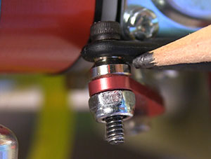
throttles to insure bind-free operation.
At wide-open-throttle this bit of play is seldom an issue. However, come back to idle and that play can add up to an unpredictable variation from a high idle to no idle. The difference between the two in terms of overall movement of the linkage can be very small. For that reason, I use zero-play linkage. I am decent at dead stick landings but realistic enough to not push my luck.
Another important consideration when designing throttle linkages is dealing the vibrations of the gas engine. Whatever we tighten up the vibrations work to loosen. To combat that users of gas engines become very familiar with things like thread locking compounds and nylon insert nuts.
There are several types of throttle linkages supplied with airplane kits today but they usually have points that could be susceptible to vibrations. With all this in mind I kept coming back to ball links as my preferred hardware for most linkages, including for the throttle. Using ball links secured with bolts and nylon insert nuts not only has zero play, they effectively defeat vibration. I most often use 4/40-size components for my throttle linkages simply because I like the somewhat larger ball and socket components that I think are more durable over the long term with frequent use.
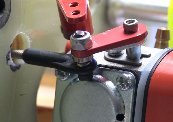
Installing ball links is not difficult though confined spaces can make it a tad more challenging as happens with some airframes. In most cases there are four components of a ball link – the ball link itself, a small metal pylon that prevents contact of the ball link body and the servo or control arm, a bolt and matching lock nut.
The most common mistake I see in ball link installations is the pylon being installed upside down. This cone-shaped piece is meant to have its small end against the ball and the wide base against the servo or control arm. This is a spacer that gives the body of the ball link room to move around the ball without interference. When the ball link is used with a double control arm like we see on larger airframes the pylon is not used.
In a few cases I have had to bend the rod to which the ball link is mounted slightly to prevent the rod or ball link body from rubbing against something. If a bend like this is needed do it before you set the final end points and travel.
To avoid running a servo against its limit on either the high or low end it is important to set the overall length of the linkage with the carb and servo at half throw. Establishing half throw on the servo is easy. To find half throw on the carb arm I just move it back and forth through its full movement and eyeball the halfway point. I know this is not absolutely precise but I have never had an issue using this “center point” of the throttle arm movement.
I generally use one of the shorter arms that come with the servos as they are plenty strong and sized right for this task. I attach the linkage at the servo to one of the outer holes depending on the available space around the linkage. The throttle arm on the carb usually only has one or two holes available but when given a choice I go to the outside hole there as well. That maximizes the overall movement of the linkage with less throw of the servo itself and makes it easy to avoid maxing out the servo.
Then with the linkage bolted in place I use the transmitters servo travel settings. Move the throttle stick to full travel (make sure it is in the right direction!) and use the end point adjustment to back the servo down until it is not reaching the end of the available travel in the carb. Bring the stick down to idle and again use the travel adjustment to be sure the servo is not pushing against the physical limit of the servo.
This travel setting is preliminary and will be refined once the engine is running. There is no good way to set the end points for an engine without it running. The points at which the engine reaches full RPM will in all probability be under the end point we set earlier. The same will happen when we try to bring the engine down to idle. That end point will have to be raised to where the carb will continue to idle rather than stop.
Taking the time to build a solid, zero-play throttle linkage can save lots of headaches later in the life of a model. If you have never had a throttle linkage break or bind up you may not understand the urgency with which those with such an experience go after building a better linkage system. It’s up to you but I suspect that nearly all of you can do without trying to get a crippled plane back to the ground in one piece.
Have a comment on this How-To? –Email Me!