


We have to drill the tabs that secure the struts and that provides practice at
putting them on and taking them off. It gets easier with experience.
Text, photos and video by Tom Hintz
Posted – 3-9-2015 One of the liabilities of superior covering job is that hard points to which components like the struts and landing gear are attached can be difficult to find. I looked at the instruction manuals for larger scale versions of the Bill Hempel ¼-scale L-4 Grasshopper but while the parts appear similar, their mounting positions on larger scale planes differ from this ¼-scale Grasshopper. While this slowed assembly somewhat a little help from Bill Hempel and another L-4 Grasshopper builder I am able to show you where these mounting points are in the accompanying photos and video so you can get your Bill Hempel ¼-scale L-4 Grasshopper built a little faster and perhaps with more family-friendly language in the shop.
One of the impressive things about the Bill Hempel ¼-scale L-4 Grasshopper is the super-tough steel control horns that are included. I think we get these high end pieces in this kit because they are standard fare on the huge planes Hempel offers. These control arms might be overkill to some degree on a ¼-scale plane but they do mean that we should not have to worry about a failure. Because there are three of these relatively steel pieces at the tail I will be careful with CG and make sure we have that right before the maiden flight.
I measured the threaded rods and found that a 5/32” drill opens the pre-drilled holes in the rudder, elevators and ailerons so that the rods just slide through without play. After drilling I added a drop of thin CA to each hole to stiffen the hardwood up a bit more before installing the horns.
I installed the rudder at this point, using 30-minute epoxy to set the pin hinges in place. I thought I would do the pull-pull system now but didn’t have the arms for the servo end so we will come back to the pull-pull system in a future segment.
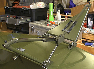
People get a little freaked out when confronted with Cub “articulated” landing gear but pre-assembly of the two main pieces make that unnecessary. The hard points for mounting the main gear to the bottom of the fuse are easy to find and can be seen from the inside of the cockpit. The only thing to trip you up is trying to assemble the sliding arms after screwing everything down. The sliding joint needs to be assembled before installing the gear. You should clean up these sliding pieces if need be and lightly grease them to be sure the assembly moves smoothly. Screw the assembly down and that is nearly all there is to the main gear.
I went through the landing gear checking
for good fit and secure locking bolts. Lots
of Loctite helped, or so I thought.
Look in the photos and video and you can see the rubber O-rings used to control the action of this landing gear suspension. These O-rings do not come with the kit but you can get them from many on-line sources very cheaply. I used #217 standard O-rings and started with only put one ring on each stud position. I expect to add at least one more at each position when the Bill Hempel ¼-scale L-4 Grasshopper is fully assembled and up to its full flying weight.
The wheels run on stout-looking pins that are retained in the gear leg with a set screw. I replaced that set screw with a socket head bolt so I can be sure to get this tight. I also filed a flat for the bolt to seat in to further secure the wheels. These are nice looking (so expensive) wheels and I do not want to watch one of them disappear into the forest.
To install the tail wheel bracket we have to find the hole into which the forward tang of the wire assembly goes. After that we install two saddle brackets with the included wood screws. I placed the rear most bracket first as that one is easy to center on the bottom of the fuselage. Then the second saddle bracket can be placed on the wire near the upturned tang. To enhance the durability of the tail wheel installation I drive the screws most of the way in then back them out one at a time to put a drop of thin CA in the hole. Drive the screws in all of the way and you have a much tougher installation.
There is a flat aluminum bracket that gets screwed to the bottom of the rudder close to the fuse. I also toughen these two holes up with thin CA. You get a pair of springs that actually “steer” the tail wheel when the rudder moves. The trick with these springs is to keep their overall length the same so the tail wheel stays aligned with the fuselage. I bend the last ½” on both ends of both springs to about 90-degtrees and then insert those ends in the brackets before wrapping the spring tail around the wire at each bracket to secure them.
There is a wheel collar at the end of the wire that actually keeps the tail wheel from falling off. I replace the set screw that secures that collar with a hex head screw that allows me to tighten it much more securely without stripping.
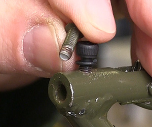
I swapped out some screws for hex-head
bolts for extra security.
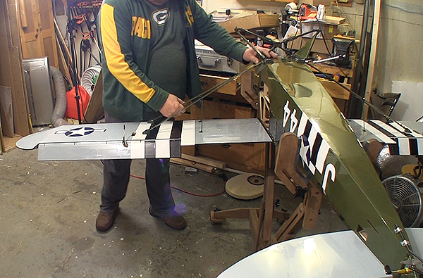
Locating the pre-installed hard points to which the struts are attached took the longest. See the video below for a better look at where these points are. All of these points have metal blind nuts installed because these are functional struts and need to be properly secured.
The two-piece struts go together near the bare end. One piece in each set is flattened along the edge so it fits into the other half and can be secured with a bolt. As with all of the fasteners on the struts, snug them down but leave them loose enough to adjust the position slightly during installation. Both strut sets are identical but one is installed upside down so that the bare end points toward the mounting tabs located just ahead of the rear pivot of the main gear of both sides. You will note that there is no hole in the end of the struts or the mounting tabs. Once everything is installed and in the final position we have to drill this hole so it can be secured with a single bolt when assembling the Bill Hempel ¼-scale L-4 Grasshopper for flight.
Leave all of the strut brackets a little loose so they will self-align later. The two mounts closest to the wing root can be enlarged slightly with an awl or similar tool to make inserting the wire brace easier. I also found that cutting off some of the excess wire from the foot that actually goes through the bracket on the wing also eases installation during assembly for flight.
Another tip for easing the initial assembly is to round the edges of the fixed tab so it slides into the strut tubing easier. I just put the tab in a vise and used a fine file to ease the corners. Then just prior to assembly I rubbed a little grease onto the tab to further ease the initial installation.
With the wings installed, including the wing bolt installed inside of the cockpit, make sure that the strut is fully seated over the mounting tabs at the main gear. Once satisfied drill a hole (for a 6/32 bolt) though the tab using the hole in the strut end as a guide. For flight we install a 6/32 bolt and insert nut to secure this connection.
This strut system makes assembling the Bill Hempel ¼-scale L-4 Grasshopper or taking it apart very easy as the only fasteners that we deal with are the wing bolts themselves and the one bolt at the end of the strut by the main gear. The wire support slips out of its mounts on the wings surface and the whole strut assembly lays flat. Easy to use, easy to transport.
Have a comment on this review? –Email Me!