

Getting the horizontal stabilizer aligned correctly goes a long way towards making
a plane respond to control inputs predictably.
Text, photos and video by Tom Hintz
Posted – 5-19-2015
One of the realities of Almost Ready to Fly (ARF) planes is that some assembly will be required to minimize the already large box to better fit shipper’s cargo aircraft and trucks. A prime way to shrink the shipping box is to leave installing the horizontal stabilizer to the purchasing hobbyist. While this makes perfect economic sense it also introduces a great way to screw up the handling of an airplane. Get the horizontal stabilizer and the elevators attached to it out of alignment with the rest of the air frame, particularly the wing, and your new plane will roll out of loops and other odd things that might have your field marshal administering a Breathalyzer test. The good news is that getting this installation right is not difficult if you take your time and follow a simple procedure.
Note: Some kits like my Hangar 9 PA-18 Super Cub used in this story have an enclosed slot into which the horizontal stab is inserted. Others have a connector piece at the tail end of the horizontal stabilizer slot that you have to cut out and usually glue back in after the stabilizer is installed. This procedure works with either type of construction.
To install the horizontal stab accurately we need reference points from which to measure and a horizontal line that represents the wing to match the horizontal stab to. The logical thing to use is the wing itself but with larger planes the size of the wing can make this awkward if your shop is not oversized as well. Also there may not be sharp, repeatable points on the wing tips from which to measure. Whenever possible I use a wing tube for this purpose.
The first thing is to get the wing tube centered in its mount. Once centered lock it in place with plastic tie wraps or tape on either side of the structure through which it passes. Next, put the horizontal stab in its mounting slot and get its rear edge centered in the fuselage. Use a pencil to make small witness marks on the horizontal stab on either side of the fuselage at its rear edge that gives us a visual indication that it is still centered.
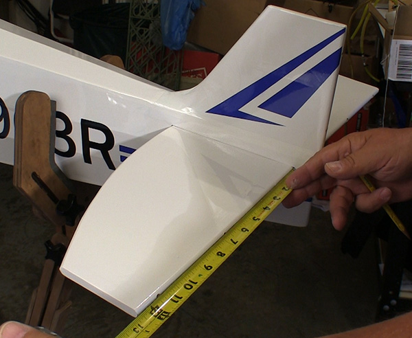
Now measure from the ends of the wing tube to the rear corner of the horizontal stabilizer and adjust its angle to the wing tube until both sides are exactly equal. As you are doing this keep track of the center marks to be sure you have not moved the stab out of its centered position. When certain that the stab is centered in the fuse and square to the wing tube add witness marks at the stabs forward edge where it meets the fuse on either side.
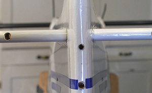
Looking from behind you can see if the
stab is parallel to the wing tube.
While the stab is aligned look at the stab from the rear and align its upper surface with the bottom of the wing tube. The wing tube and the surface of the stab should match all the way across. The main thing we are looking for here is a major miss alignment that requires working the saddle to correct it. I have found that in most cases miss alignments are small and can be “tweaked” out during final assembly as the epoxy cures.
Remove the stab and slice the covering on a line 1/8” or so inside the witness marks. We want the covering to extend into the fuse so there is no bare wood line showing. This is also a good time to iron down the covering at the new cut lines so it doesn’t wrinkle when inserted.
Paint the exposed wood with 30 or 45 minute epoxy on both sides and the front and rear edges. If the instructions had you cut away the piece at the rear of the slot you can also paint epoxy in the stab saddle because you and slide it in from the rear. On my Cub the stab is slid in from the side so the saddle is left bare. When you slide the stab into position there will be some squeeze out so use alcohol and paper towel to clean up excess epoxy.
Carefully measure to get the stab centered side to side and square to the wing tube. When the stab is aligned sight down the fuse, setting the wing tube on the top edge of the stab from your point of view. If there is a small miss alignment add a piece of masking tape from the low end of the stab to the vertical stabilizer. Pull the tape just tight enough to draw the stab up to match the wing tube. Leave the tape in place until the epoxy is fully cured.
Remove epoxy that has worked out of the joint with alcohol and paper towel. Get out your tape measure and check the alignment one more time before the epoxy sets up. When satisfied that the stab is aligned correctly, step back and keep your hands off until the next day at least.
I know this looks like a long procedure but it really isn’t and goes quickly once you do it a time or two. What is certain is that taking the time to get your horizontal stabilizer aligned correctly goes a long way towards making your plane fly correctly. A miss aligned horizontal stabilizer shows itself when the plane tries to roll out of a loop but the impact of that assembly error forces you to add corrective inputs to many common maneuvers. It is worth your time and effort to get this right the first time so you can enjoy your plane for years afterwards.
Have a comment on this story? –Email Me