


This is where my confidence in this kit went off the rails. They call for just looping the braided cable through the metal plate horns
which is way stupid and insures a failure. I changed it all out for real pull-pull cables with ball ends.
Text, photos and video by Tom Hintz
Posted – 10-1-2015
All that remains to be done on the wing is to install the forward locater pins, the bolts and blind nuts at the trailing edge. To do that accurately I needed to install the horizontal stabilizers. Guided by the included template I installed the anti-rotation pins in the horizontal stabilizers. Since these stabs are not removable I used the long set time Epo-Grip epoxy to glue the stabs and the tubular aluminum brace in place and let that set up overnight.
My ESM 88” Zero will be powered by my DA50R so using my template I drilled the firewall for the mounting bolts. The prop washer to firewall distance listed in the manual is 160mm and I already have those standoffs so I mounted the motor with hopes of not having to remove it again. That hardly ever works out but I hope for it with every plane I build.
One of the first discoveries during this installation is that a Pitts style muffler just will not work with the DA50R on the ESM 88” Zero without removing a large piece of the firewall. This is one of the compromises of not having a motor box as we see on most gas models these days. It is looking like the cowl will be a crowded place when all is said and done.
With the motor in place I was able to make up the throttle push rod. I used a carbon fiber tube and titanium ends (Central Hobbies) because it is very light and very strong. There also is no flex which gives me a very predictable throttle response.
The missing cowl ring arrived so that was glued into the cowl using the 40mm setback listed in the instructions. Initially I am used CA to mount the ring 40mm in from the rear edge of the cowl. Then I mixed up some of the Epo-Grip Matrix, epoxy infused with glass fibers for super durability. Using the pallet knife I was able to lay in a nice fillet of the Epo-Grip epoxy around the edge of the cowl ring.
The cowl with ring is intended to be installed from the front with screws into the firewall but that might change when the muffler is installed. I may have to go to blocks on the firewall placed to accept screws through the outside of the cowl.
I should note that I am opting to stay with the tail wheel assembly included with the ESM 88” Zero kit rather than a retractable unit. Part of this is to keep the cost down but also to eliminate any extra weight that far back on the ESM 88” Zero. War birds tend to be tail heavy so throughout this build I am thinking “weight forward” whenever possible.
I had to get creative with servo arms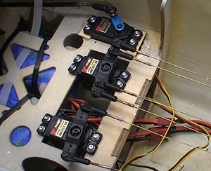
to avoid conflicts as they went through
their travel.
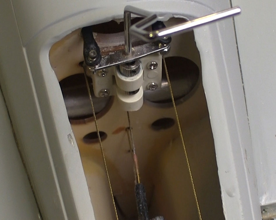
The ESM 88” Zero does not have external control horns on the tail surfaces and I agree that is a good look for this plane. Making all that happen means 3 sets of pull-pull cables all installed through a relatively small cover at the tail which makes this look like it might be the toughest part of the build. Plus the instructions call for simply looping the included braided steel cable through the steel control horns on the rods that move the surfaces and tail wheel. The idea of a braided steel cable constantly working on the edge of a steel hole is simply stupid on a good day and will at some point end in disaster so I again veered sharply away from the instructions.
I like using the Sullivan pull-pull kit that comes with 2/56 brass ends that are soldered to the included brass-plated (solders easily) cable to which I add 2/56 ball links. To make the connection at the steel control horns in the tails I took the time to drill and tap them for the 2/56 bolt that secures the ball link. I also am adding nylon insert locking nuts for additional security. The access to the tail cavity is limited and gets a bunch worse when the tail wheel assembly is installed. Once the ESM 88” Zero is together I’d just as soon never see the insides of that cavity again.
Though putting the tail section together was less difficult than I anticipated it is by no means a walk anywhere near a park. The illustrations in the “instructions” provide a general idea of where everything goes but be ready to apply a little “seat of the pants” engineering and a solid dose of common sense in the rear of the ESM 88” Zero. I think I put the tail wheel assembly in differently than the instructions are trying to indicate but it’s hard to tell. I pretty much gave up on the instructions and started routing cables and locating the tail wheel bracket where I thought it made the most sense and did not compromise other components or cables.
The wire that the controls are made from is pretty hard and chrome plated so it is best cut with a small grinder. Also, to bend the rudder shaft I found that heat from a propane torch makes this easy. Remember when making this bend on the rudder control to do it 90-degrees to the pull-pull arms that are factory soldered (or brazed) to the wire so the arms are square to your servo when the rudder is centered.
I assembled one end of all six cables and attached them at their finish point in the tail. I cut all of the cables several inches longer than needed so I could fit them at the servo to get a better fitting cable the first time.
You will note in the photos that the rudder servo has four cables attached to it. The outer two go to the rudder and the inner two to the tail wheel. A friend who built an ESM 88” Zero of his own told me about this setup and it makes sense because we need way less throw at the tail wheel than the rudder.
The cowl dimensions for me ordering a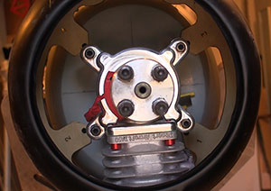
Bisson muffler that actually fit.
I am using an AR9110 9-Channel DSMX PowerSafe Receiver (#SPMAR9110) for this plane as it provides the redundant battery capability without adding an external system. Also, this receiver comes with three satellite receivers, each on a different length cable. I am using two (BuddyRC) 7.4V, 5000mAh LiPo packs for electrical power. The switch included with this receiver is specially designed so if it fails it fails to an On configuration so we do not lose control.
To provide remote ignition cutoff capability I am using an Ultra IBEC (Ignition Battery Eliminator Circuit) from Tech-Aero. This simple harness not only provides remote ignition kill but it also eliminates the ignition battery pack because it provides that power to the ignition box from the receiver. To eliminate interference this unit has effective filtering built in so the ignition does not mess with operation of the receiver. People have this stuff figured out! The Ultra IBEC also has a LED that you can put someplace to show when the ignition is armed. In my only true scale-related action I set this LED into the printed dash board that came installed in the cockpit.
As I was preparing this segment for publishing the Bisson muffler arrived so I can get going on the next and hopefully last segment of the build portion of this review. I was also notified that the Robart electric retracts have shipped so with their arrival I should have all of the needed pieces in hand. Stay tuned!
Have a comment on this review? –Email Me!